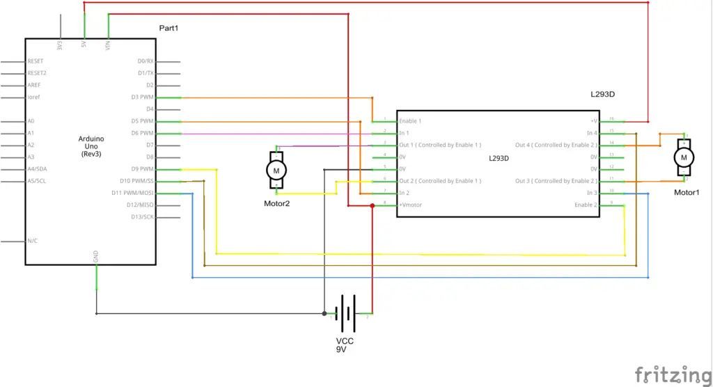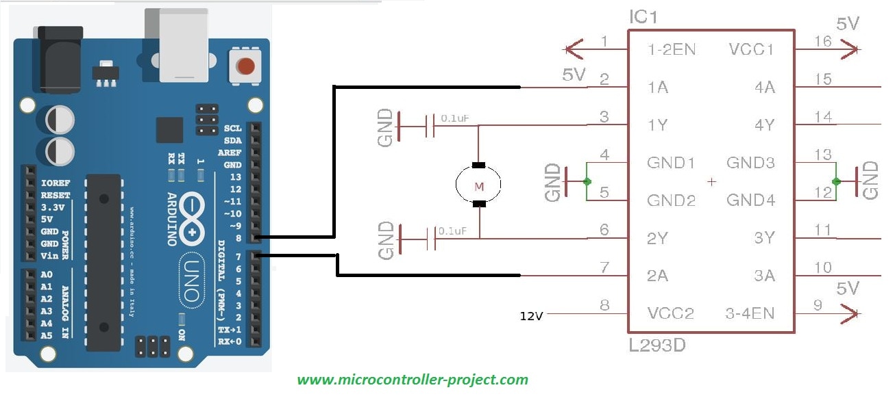

The further detail about L 293D motor driver/controller will be given later in this tutorial.
#L293D MOTOR DRIVER CIRCUIT DIAGRAM DRIVERS#
L 293D plays a vital role in electronics era and has several different applications e.g relay drivers, DC motor drivers, stepping motor drivers etc. L-293D has different features including internal ESD protection, large voltage supply range, large output current per channel, high noise immunity input etc. If the enable pin is low, there will be no output. If L 293D enable pin is high, its corresponding driver will provide the desired out. By changing the polarity of applied signal motor can be rotated in either clockwise or counter clockwise direction.

It has two enable pins and they should be kept high in order to control the motor. L-293D has to builtin H-Bridge driver circuits and is able to control two DC motors at a time in both clockwise and counter clockwise direction. Motors usually operates on this higher current. Motor driver usually act as current amplifier because they receive a low current signal as an input and provides high current signal at the output.

It is able to drive load having current up to 1A at the voltage ranging from 4.5V to 36V. Today I am going to given elaboration on Introduction to L293D. L 293D is basically a high current dual motor driver/controller Integrated Circuit (IC). Hello everyone! I hope you all will be absolutely fine and having fun.


 0 kommentar(er)
